


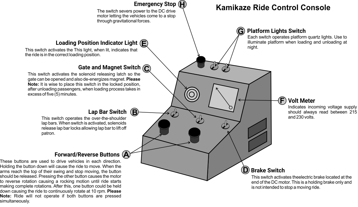
Ride Operators ARE GIVEN extensive on the job training. It’s the only way to ensure that new operators are competent to handle the ride controls. That said, this section of our staff induction goes over the components of the ride control box and what is expected of a ride operator before being given hands on, on the job training under the guidance of Corbin. Please study the control box below and acknowledge that you have read and understand the Kamikaze Ride operational requirements and procedures.
RIDE CYCLE
When operating the Kamikaze Amusement Ride for patrons, the operator must see the following steps are followed, before, during and after each ride cycle.
a) Allow maximum of 32 patrons to enter the ride.
b) Check to assure all shoulder bars are locked and secondary latch is below lock point.
c) Assure gates are closed and latched.
d) Check to make certain all entrance and exit gates, chairs are closed and all non-riding patrons are behind fence.
e) No patrons are allowed on platform during operation.
f) Assure all lap bar, gate, and brake switches are in proper position for operation.
g) Start forward and reverse movement until ride has completed a full revolution.
h) Allow maximum three (3) revolutions in each direction.
i) Bring ride to a stop by pressing button of opposite direction (indicator on control panel should be lit showing ride is in loading position).
j) Lock brake.
k) Activate lap bar and gate release.
l) Assist passengers in exiting ride.
OPERATION OF PASSENGER RESTRAINTS AND SAFTEY DEVICES
a) Activation of Lap Bars – To release bars, it is necessary to activate switch on control panel. This switch energizes solenoids located between every two seats. Releasing the gear lever allowing the shoulder bars to lift with the aid of a gas cylinder. When the shoulder bar release switch is turned off, releasing solenoid, gear levers fall on large ring gear allowing shoulder bar to rotate in the down direction only. Upward pressure on lap bar will cause gear bar to lock tight on gear ring.
b) Mechanical Back-Up Shoulder Bar Lock – The Kamikaze amusement ride is equipped with a secondary lock system. This latch is designed to prevent shoulder bars from raising any higher than half-way, in the case of a failure of the automatic latch system. Under normal operation this latch is not an active lock for the shoulder bar. In the event that the primary latch has failed, the plunger rod in lock mechanism will drop in locking hole (with spring pressure). When lap bar raises to the half-way point, further travel of shoulder bar is prevented.
c) Shoulder Bar Release Safety System – The kamikaze is equipped with an electrical safety system that prevents the operator from releasing shoulder bars unless vehicles are in loading position. It also includes a backup system that automatically locks shoulder bar when vehicle leaves loading position.
EMERGENCY STOP PROCEDURES
In the case of an emergency, which requires bringing the ride to a complete stop in mid-ride cycle, the operator has two (2) choices depending on the particular situation:
A. Bring the ride to a quick stop by pressing reverse button at proper time and holding until the ride has come to an almost complete top. Then allow gravity to reverse direction and pressing opposite button until ride has come down to loading position and apply brake. Note: This is the quickest way.
B. Press emergency button on top of control panel. This immediately shuts off power to drive system and allows ride to free wheel until gravity brings ride to loading position. Then apply brake. This system is used when there is an electrical emergency in the drive system.
When ride comes to a complete stop, unload passengers immediately and evacuate platform.
POWER FAILURE PROCEDURE
In the event of a power failure, ride must be allowed to allow and come to a complete stop on its own. Then the following procedures must be followed in order to allow the riders to exit the ride.
A. Locate the inspection plate for the solenoid of the shoulder bar locking mechanism.
B. Using a small flat screwdriver, insert tip into small hole in plate at a slightly downward angle until contact is made with the solenoid.
C. Using the screwdriver as a lever, pull down on the screwdriver. This will lift the solenoid releasing gear lever on both shoulder bars allowing them to be raised.
THIS IS NECESSARY ONLY IF THERE IS AN EMERGENCY SITUATION OR POWER FAILURE!
Report to proper authority anytime there is an emergency situation. The ride should not be operated again until the condition causing the emergency situation or power failure is investigated.
The Kamikaze Amusement Ride is a designed to operate with a minimum of two (2) persons. One person at the controls at all times during ride operation and one monitoring the gates and platforms. It may be necessary to have additional personnel during high traffic periods.
PASSENGER RESTRICTIONS
The following rules of conduct and restrictions are to ensure the safety of all patrons. A sign should be posted in full view of all potential riders listing a minimum, of the following information:
a) No riders under the age of seven (7) years are allowed unless occupied by an adult.
b) No riders under 48″ tall allowed
c) No food or drink allowed on the platform or ride.
d) Remove all loose articles from person before entering ride.
e) Persons under medical care or with neck or back injuries are not allowed to ride.
f) No pregnant women allowed to ride.
g) If rider is too large for secondary restraint system to latch properly, they will not be allowed to ride.
h) Patrons must keep hands inside vehicle at all times.
PASSENGER CAPACITY
The Kamikaze Amusement Ride is designed for a maximum passenger load of 32 passengers, one (1) per seat. No passenger should be allowed to ride unless secondary latch is past the latch point. Each passenger seat is equipped with the following safety equipment:
a) Head area padding
b) Shoulder restraint with padded chest bar
c) Self adjusting, spring operated solenoid released latching system (off set lever and gear system).
d) Back-up mechanical shoulder bar lock – automatic spring lock with manual release
e) Gate closing access area to seating compartment.